

A well-matched CNC lathe machine earns its keep on one measurable outcome: parts that hold tolerance across the full production volume, shift after shift, in everything from free-cutting steel to aged Inconel 718. Machines that fail this test fail for engineering reasons – marginal structural rigidity, uncompensated thermal drift, a spindle tuned for brochure speed ratings instead of low-rpm cutting force – and no controller feature fixes those after the purchase order is signed. The selection logic that follows mirrors how a process engineer evaluates a machine tool on the shop floor: match the machine architecture to the workpiece, audit the features that actually govern accuracy, and verify performance before the foundation bolts are torqued.
How Should Production Needs Shape Choosing the Right CNC Lathe?
Machine selection starts with the workpiece, not the catalog. Three questions narrow the field faster than any specification table:
- What tolerance band must the part hold in production – and for how many consecutive pieces without touching offsets? A 0.005 mm concentricity requirement on a thin-walled sleeve is a rigidity and thermal problem, not a controller-brand problem.
- What is the material and its metallurgical condition? Solution-treated nickel alloy cuts nothing like the same alloy after aging; a machinability rating shift of that magnitude changes the required low-end torque, the tooling budget, and sometimes the bed construction worth considering.
- What takt time does the cell demand? Cycle-time math – cut, index turret, load, unload – decides whether a two-axis lathe, a live-tooling turning center, or a twin-spindle configuration belongs on the line.
Shops that answer those questions first end up comparing two or three lathe machines instead of twenty, and the comparison turns on engineering substance: box way versus roller linear guide, the spindle torque envelope, turret indexing repeatability, and the thermal behavior of the casting over a full shift.
Flat-Bed and Slant-Bed Two-Axis Lathes
A flat-bed lathe still earns respect for heavy roughing and interrupted cuts on large-diameter work – its box ways absorb the shock of scalping a forged billet without transferring it into the spindle bearings. The slant-bed layout dominates mid-size production for a different reason: chips slide off a 30-45° incline instead of pooling on the saddle, where they get re-cut and weld onto the insert edge. Re-cut chips are a hidden scrap driver that never appears on a quotation, which is why high-volume shops running gummy alloys like 304 stainless favor steep slant beds with properly sized chip conveyors.
Multi-Tasking Turning Centers with Live Tooling
When a part needs cross-drilling, milled flats, or back-face work, a turning center with a C axis, driven tools, and a sub-spindle removes the second operation entirely. That matters for concentricity: a bore and its mating outer diameter machined in one setup, in one spindle, cannot drift the way a part re-fixtured on a second machine can. CNC Turning Centers configured with Y-axis travel also handle off-center features – bolt circles on flanges, milled keyways – without turning the turret into a compromised milling head. For machining needs that already involve secondary operations, specifying the C axis at order time costs far less than wishing for it later.
Mini Lathe and Heavy-Duty CNC Metal Lathes
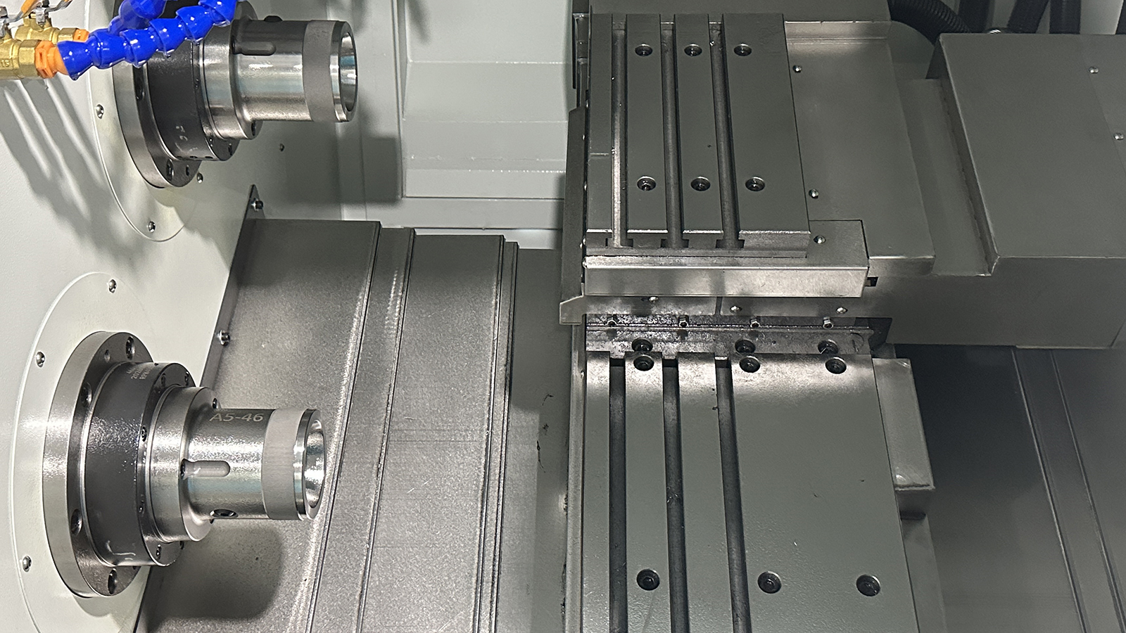
A compact gang-tool lathe suits prototypes and short runs of parts weighing a few hundred grams; a production bar-fed machine in the 50-80 mm through-spindle class runs unattended overnight. Between those poles sit the general-purpose slant-bed lathe models most job shops buy first. The honest comparison point is not swing diameter but bar capacity, chuck size, and bed length versus the longest part actually on the order books.
Which Key Features Actually Decide Long-Term Accuracy?
Spindle Speed, Torque, and Thermal Behavior
Headline spindle speed sells machines; usable torque keeps them cutting. Aged Inconel 718 turns at roughly 30-50 m/min with rigid carbide tooling – solid workholding, positive geometry, and flood coolant assumed – which on a 200 mm bar means the spindle lives at double-digit rpm, deep in the constant-torque region, for hours. A drive that sags there produces chatter, edge chipping, and scrapped nickel. Buyers should also demand spindle balance to G2.5 or better and thermal displacement compensation: sensors on the spindle housing that measure axial growth as the bearings warm and feed corrections to the offsets automatically. On machines without it, the first two hours of every shift become warm-up hours, and the tolerance window quietly pays for them.
Structural Rigidity: Box Ways vs Roller Linear Guides
The bed tells the truth about a builder. An HT300-class cast iron body, stress-relieved by natural aging or vibration treatment before final machining, holds its geometry for decades; a hastily seasoned casting moves measurably in its second year. Hand-scraped way surfaces with controlled contact-point density damp harmonic vibration in a way no amount of controller tuning can replicate. Box ways – with anti-friction coatings on the flanks to suppress stick-slip at fine feeds – remain the choice for interrupted cuts and hardened die-steel turning. Roller linear guides deliver lower friction, faster rapid traverses, and crisper fine positioning, which favors finishing work and small-part takt. Neither is universally better; the decision belongs to the cutting forces in the actual part family.
Turret, Live Tooling, and Automation Features
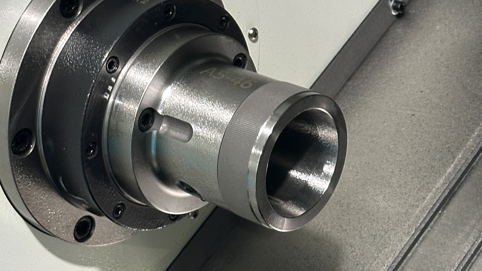
Turret indexing repeatability determines whether tool positions return predictably after every index – worn curvic couplings turn each index into a tolerance lottery. Hydraulic clamping on the turret and a parts catcher rated for the real part weight are baseline items. Beyond that, automation features rank by the downtime they kill: a synchronized bar feeder for lights-out running, a chip conveyor sized for the chip volume of the actual alloy mix (titanium floods beds faster than carbon steel), and steady rests for slender shafts where the length-to-diameter ratio pushes tool deflection past the tolerance band.
How Do Application Requirements Change the Selection?
Aerospace work in TC4 titanium rewards low-speed torque, minimal clamping distortion, and high-pressure coolant delivery; thin walls spring and grab, so machine damping and cut strategy matter more than top speed. Automotive hubs and shafts run on takt time – quick-change tooling, reliable chip evacuation, and gantry or robot loading decide the effective output rate. Medical implant work lives at the small end: gang-tool or Swiss-style configurations, bar stock, and surface finish requirements down to Ra 0.4 µm. Oil-and-gas couplings want mass, swing, and box ways that shrug off interrupted cuts in 4140. Builders like YASHU publish application-specific configurations for exactly this reason – the right machine for a titanium flange is not the right machine for a brake hub – and reviewing CNC Turning Centers by application family short-circuits a long list of mismatched quotes.
What Matters When Buying New vs Used CNC Lathe?
A used CNC lathe can be a bargain or a donor organ. The inspection list is short and merciless: spindle runout at the nose measured with a 0.5 µm-class indicator, way wear checked across full travel with a precision level, and – most revealing of all – the backlash compensation values stored in the control. Large or climbing compensation numbers mean the ballscrews and ways are worn and still degrading. Ask for hour-meter readings, maintenance logs, and any ISO 230-2 commissioning or rebuild test charts before the price is even discussed.
New-machine budgeting fails when it stops at the invoice. Freight and rigging, a three-phase power drop, foundation work, tooling (commonly 15-20% of machine cost on turning applications), and spare consumables all land before the first chip. Manufacturers such as YASHU that document HT300 casting practice, way-scraping standards, spindle balance, and pre-delivery accuracy testing on every CNC lathe machine shorten the due-diligence loop considerably – the acceptance data either exists or it does not.
FAQs
1. How is positioning accuracy on a lathe actually verified?
By laser interferometer per ISO 230-2: bidirectional runs along each axis, reporting both positioning accuracy and repeatability. A supplier who cannot produce current charts is asking for trust in place of measurement.
2. Box ways or roller linear guides for hardened die-steel turning?
Box ways. Their damping handles interrupted engagement in the HRC 50+ range; roller linear guides excel at fine positioning and rapid traverses for finishing cycles, but they transmit more vibration back into the cut.
3. Can live tooling be added to an existing two-axis lathe later?
Realistically, no. A true C axis is integrated into the spindle drive and encoder architecture, and driven-tool coolant paths are cast in at build time. The capability has to be specified when the machine is ordered.
4. How much spindle power does Inconel 718 need?
Condition-dependent. Aged 718 at 30-50 m/min with deep roughing passes can load a spindle near its constant-torque ceiling on diameters above 100 mm; solution-treated material tolerates higher speed and lighter duty. Size the drive to the worst case in the part mix, not the average.
5. What kills a used-lathe deal fastest?
Runout beyond a few microns at the spindle nose, way wear visible across the travel, and backlash compensation values that keep climbing – that machine is worn and still moving.
References
- International Organization for Standardization. (2014). Test code for machine tools – Part 2: Determination of accuracy and repeatability of positioning of numerically controlled axes (ISO 230-2:2014, Edition 4). Specifies bidirectional laser interferometer methods for positioning accuracy and repeatability of NC axes – the basis for the acceptance charts above. https://www.iso.org/standard/55295.html
- International Organization for Standardization. (2020). Test code for machine tools – Part 3: Determination of thermal effects (ISO 230-3:2020, Edition 3). Defines the ETVE test and thermal distortion tests for rotating spindles and moving linear axes – the procedures behind the thermal drift discussion above. https://www.iso.org/standard/73291.html
- International Organization for Standardization. (2016). Mechanical vibration – Rotor balancing – Part 11: Procedures and tolerances for rotors with rigid behaviour (ISO 21940-11:2016). Establishes the balance quality grades (G) and residual unbalance tolerances for rigid rotors; the G2.5 spindle requirement cited above is defined here. https://www.iso.org/standard/54074.html
- The American Society of Mechanical Engineers. (2005, reaffirmed 2020). Methods for performance evaluation of computer numerically controlled machining centers (ASME B5.54-2005 (R2020)). Establishes terminology, environmental treatment, and the acceptance testing (runoff) and periodic verification test series for CNC machining centers, including positioning accuracy and angular deviations. https://www.asme.org/products/codes-standards/b554-2005-methods-performance-evaluation-computer