
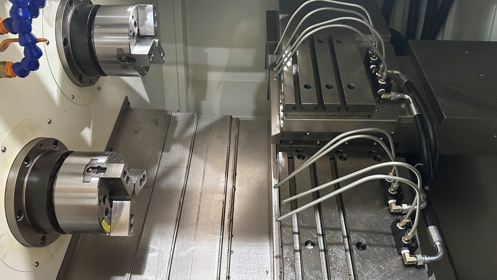
A CNC lathe with live tooling collapses two historically separate machine tools – a turning center and a milling machine – into one continuous setup. When a driven tool station engages while the main spindle indexes to a locked C-axis angular position, cross-drilling, axial milling of flats, and rigid tapping can all finish before the workpiece ever leaves the chuck. For process engineers balancing cycle time against concentricity and feature-to-feature true position, the question is no longer whether to adopt live tooling, but how to configure the turret, tooling interface, and driven-tool power path so that single-setup accuracy holds across a production batch.
Why Does Live Tooling Beat Separate Milling and Turning Setups?
Every time a cylindrical part is unclamped from a lathe, transferred to a machining center, and re-clamped in a vise, the datum reference frame shifts. A 0.02 mm reclamping error sounds trivial until it stacks into a 0.05 mm true-position deviation on a cross-hole feature – enough to push an aerospace bracket or a medical implant outside the tolerance band. A CNC lathe with live tooling eliminates that transfer entirely: the workpiece stays gripped in the spindle chuck through every turning, milling, and tapping operation, so the geometric relationship between the turned diameter and the milled flat is established by machine kinematics rather than operator re-clamping discipline.
The structural foundation matters here. A rigid HT300 cast-iron bed, aged to release residual casting stress, keeps the spindle centerline stable relative to the turret guideways – whether the box-way slides absorb a heavy roughing cut or a live tool pecks a cross-hole. Box ways versus roller linear guides trade a measure of rapid traverse speed for far higher damping capacity under interrupted cutting, the exact condition live tooling creates when a driven milling cutter enters an indexed workpiece. Shops that have fought chatter on a roller-guide lathe during live milling recognize why the box-way configuration remains preferred for aggressive mill-turn work.

How Do Driven Tools and Turret Configurations Shape Turning Center Performance?
The turret is the mechanical heart of a live tool lathe. It must index static turning tools with sub-arc-minute repeatability and simultaneously route power – typically through a gear train or direct-drive coupling – to whichever driven tool the program calls. Two interface conventions dominate: the VDI tooling system, with its standardized DIN-based mounting flange and central drive, and block-style tool holders bolted directly to the turret face. Each carries trade-offs in tool-change speed, available live-tool RPM, and the number of live stations the machine builder can package.
C-axis capability is the enabling feature. Without a controllable, braking spindle that locks at a precise angular position, a driven tool can only mill on-center – it cannot drill off-center or tap a cross-hole with controlled orientation. The KX-46J Y-Axis CNC Turning Center (4+4 Live Tools) illustrates how a Y-axis stroke deepens this capability: the driven tool can travel off the centerline to machine keyways, flat pockets, and off-center hole patterns without repositioning the workpiece, which directly shortens setup time and widens the range of complex parts a single machine can complete.
What Live Tool Technology Delivers for Precision Machining Across Industries?
Industry demand drives the configuration. Aerospace shops cutting titanium engine brackets value the damping of box ways and the ability to mill lightening holes and bracket flats without a second machine. Medical device manufacturers machining orthopedic implants from cobalt-chrome alloys depend on single-setup concentricity between a turned taper and a milled locking feature – a relationship reclamping would compromise. Mold and die builders use live tooling to cut water-line slots and ejector-pin cross-holes on cylindrical cores in one fixturing, avoiding the stack-up error a second clamping introduces.
Machinability ratings, the ISO 513 S-group and H-group classifications, and the resulting cutting forces all feed back into tool-life expectations. A driven tool that runs at 6,000 RPM tapping M3 threads in aluminum enjoys a very different duty cycle than the same station cross-drilling a hardened H13 core at 4,000 RPM with through-tool coolant delivery. Properly matched live tool holders – precision-balanced for high-speed rotation – suppress the harmonic vibration that otherwise destroys driven-tool bearings and degrades surface finish. Where YASHU configures a live tool CNC lathe, the turret station count, driven-tool power rating, and coolant pressure are matched to the dominant workpiece mix rather than specified from a generic catalog page.

Which Tooling Interface and Live Tool Holder Selection Maximize Tool Life?
Tool life on a live tool lathe is governed less by the cutting insert than by the rigidity of the power-transmission chain behind it: turret face, tool holder shank, driven-tool coupling, and bearing support. A loose or worn VDI interface transmits runout straight to the cutting edge, producing chatter, accelerated flank wear, and Ra values that climb well past the 1.6 µm target on a milled flat. Inspecting mating surfaces for debris, checking the taper contact zone, and verifying that the locking mechanism still pulls the holder flush are routine tasks that separate a productive shop from one fighting mysterious tolerance drift.
Through-tool coolant delivery – often at 70 bar or higher – is not a luxury on live tooling; it evacuates chips from a blind cross-hole and stabilizes the cutting edge thermally. Combined with a rigid holder and a balanced driven tool, it lets a single setup hold tolerances a conventional CNC lathe cannot reach. The KX-46J Y-Axis CNC Turning Center (4+4 Live Tools) pairs this coolant strategy with a Y-axis and dual live-tool groups so a complex part moves from bar stock to finished machined part without an intermediate handling step.
Selecting the Right Live Tool for Your CNC Lathe Machine
Configuration decisions should trace back to the workpiece, not the brochure. The sequence below keeps selection tied to measurable shop-floor outcomes:
- Map the feature set: count the off-center holes, flats, keyways, and threads the part actually requires, then select a turret with enough live stations to cover them without mid-cycle tool changes.
- Size driven-tool torque and RPM to the hardest workpiece material in the queue – an S-group alloy demands far more spindle and driven-tool rigidity than an aluminum hub.
- Confirm C-axis and Y-axis availability before committing; cross-drilling and off-center milling both depend on controllable, lockable spindle orientation.
- Verify the tooling interface matches the holder inventory already on the shop floor to avoid a parallel tooling system that inflates setup time.
- Specify through-tool coolant pressure sufficient for the deepest blind feature, not merely the shallowest.
YASHU builds these turning machines around production realities rather than a single best-case part. The range of CNC lathes spans bar-fed 2-axis models to Y-axis live-tool turning centers, letting a shop match machine stiffness, turret capacity, and driven-tool power to its actual mix of complex parts.
FAQs
1. How many live tool stations does a typical part actually need?
Most prismatic-on-cylindrical features – a cross-hole, a flat, a keyway, and a thread – fit within four driven stations. Parts with dense off-center feature clusters, such as valve bodies, justify the 4+4 (eight live tool) configuration. Over-specifying stations adds cost and consumes turret real estate that static turning tools need.
2. Does live tooling compromise turning accuracy?
Not when the bed, guideways, and spindle are engineered as a system. A rigid HT300 bed with aged cast iron and box-way damping keeps turning accuracy intact; live-tool stations engage only when called and lock out of the cutting path otherwise. Single-setup accuracy consistently outperforms two-machine transfer accuracy.
3. What surface finish can live milling achieve on a turned diameter?
With a balanced driven tool, through-tool coolant, and proper radial stepover, a milled flat can hold Ra 0.8-1.6 µm. Harder workpiece materials and higher radial engagement push Ra toward 1.6-3.2 µm. The ISO 21920 series defines the Ra and Rz parameters referenced here.
4. Is a Y-axis necessary, or just a premium feature?
A Y-axis is necessary whenever an off-center feature – a keyway, a flat pocket, or a bolt-circle pattern – must be machined without re-indexing the workpiece in the chuck. Without Y travel, the driven tool can only work on-center, which sharply limits the range of complex parts a single setup can complete.
5. How does through-tool coolant affect live tool life?
High-pressure through-tool coolant – typically 50-100 bar – evacuates chips from deep cross-holes, reduces cutting-edge temperature, and suppresses built-up edge formation. On hardened steel and high-temperature alloys, it can extend driven-tool life two- to threefold versus flood coolant alone.
References
- International Organization for Standardization. (2020). Test conditions for numerically controlled turning machines and turning centres – Part 1: Geometric tests for machines with horizontal workholding spindle(s) (ISO 13041-1:2020, 2nd ed.). https://www.iso.org/standard/69009.html – Defines geometric acceptance tests and tolerances for horizontal-spindle CNC lathes, supporting the single-setup accuracy and kinematic-datum arguments in the body.
- International Organization for Standardization. (2009). Numerically controlled turning machines and turning centres – Part 6: Accuracy of finished workpieces (ISO 13041-6:2009, 2nd ed.). https://www.iso.org/standard/46439.html – Specifies finished-workpiece accuracy tests for turning centres, supporting the dimensional-accuracy and concentricity claims about single-setup machining.
- International Organization for Standardization. (2015). Machine tools – Safety – Turning machines (ISO 23125:2015, 2nd ed., confirmed 2024; revision ISO/DIS 23125-1 in development). https://www.iso.org/standard/65500.html – Covers safety requirements for four turning-machine groups including work-holding and spindle operation, supporting the chuck-holding and C-axis locking discussion.
- International Organization for Standardization. (2012). Application of hard cutting materials – Classification and application of cutting tools – Designation of the main groups and groups of application (ISO 513:2012, 4th ed.). https://www.iso.org/standard/59932.html – Defines the P/M/K/N/S/H workpiece-material groups for cutting-tool selection, supporting the machinability-rating and material-matching discussion.